Example 6.1 - Shaft with shoulder

This example show how to use SimFat to evaluate the FKM Guideline (5th edition) "Example 6.1 - Shaft with shoulder". Material is of milled steel (41Cr4 after DIN EN 10083). Load is both bending and torsion load of the shaft. Dimensions are D=50mm, d=42mm, r=5mm,t=4mm, d/D=0.84, r/d=0.119, r/t=1.25. The shaft is machined with an surface roughness, Rz=10μm.
Loading is constant amplitude in both bending and torsion. The nominal stresses are at "d":
Sb = ±Sa,b = ±150MPa
Tt = Tm,t ± Ta,t = 50MPa ± 100MPa
FE Model
This example is created with Ansys and is as described in the FKM example 6.1 but with a load that give the nominal stress described above. The results from the FE model is exported with SimFat export script that is a part of the software.

Import FE results
The model is found in the install directory under "Examples". To load model right click in the 3D geometry pane or "Load Geometry" under "File".


Set component solve settings
Under the project tree to the left click on the "Geometry", this will set solve settings for all sub components in the loaded geometry to the same solve settings. Here start by setting "Evaulation method" to "FKM". When this is selected 3 panes will be present as shown below.
In the "Material", "Interphase" and "Solve Settings" pane the following properties are set according to the example.


Set load history/spectra
Right click on the "Load History" and press "Add Load Spectra". Optional change the title of load card to describe the load card. Load the result file from the "Example" directory. Set "F" to -1. Right click on the load card title and press "Add file to frame", here a second file can be added to the load card. Select the same file but chose load case 2 from the file and set "F" to 1.
The FE model is evaluated with a combined torsion and bending load, load step 1 minimum load and load step 2 maximum load. The load is the fatigue load to evaluate and is evaluated for a cycle count of N=10^6. As the load from the FE model is the fatigue load to evaluate the load factors are -1 (minimum load) and 1 (maximum load). As the load is 1D load the depth factors are set to 0.
The load history pane should look like the picture below.

Solve
Now the fatigue evaluation can be started. To start the solver press "Solve" under "Analyze" in the toolbar or press F5. The result can be shown in the "Result" branch in the project tree to the right. 
Results
The FKM approach uses utilization as the main criteria to evaluate the fatigue cases. In SimFat both the utilization and damage is calculated. The damage evaluation is based on a rewrite of the equations in the FKM guideline to take in to account the parameters and safety factor.
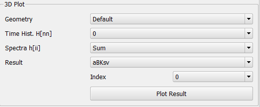
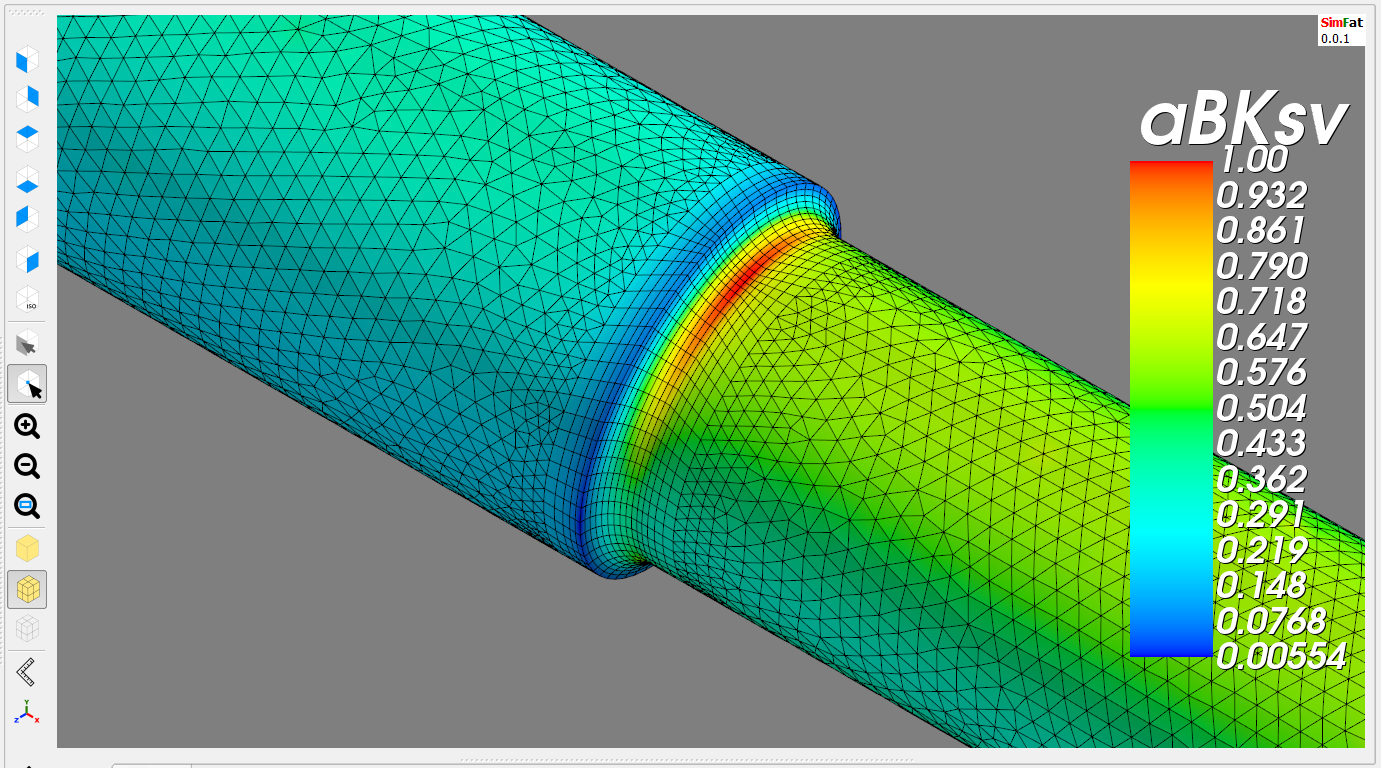
FKM utilization result
Damage result
To show the damage result for maximum principal stress, select "D" in the "Result". For evaluating the absolute maximum principal stress select 0 in the "Index" drop down. Then press "Plot Result".


Parameter details
The parameters calculated from SimFat compared to parameters in FKM example are found here. As the example is based on nominal stresses and SimFat calculate on the node (notch) stresses, some constants are not in both cases. Therefore only the constants found in both are shown here.
There are a minor difference of 2% of the utilization aBKsv, this is seen acceptable as the FKM example is based on nominal stress approach and the evaluation in SimFat is based on node (notch) stresses.
| Constant | FKM Example | SimFat | |
| Material properties | Rm [MPa] | 895 | 895 |
| fW,σ | 0.45 | 0.45 | |
| σW,zd [MPa] | 403 | 403 | |
| fW,τ | 0.577 | 0.577 | |
| tW,s [MPa] | 233 | 232.5 | |
| Design parameters | aR,s | 0.22 | 0.22 |
| Rm,N,min [MPa] | 400 | 400 | |
| KR,s | 0.857 | 0.857 | |
| aM | 0.35 | 0.35 | |
| bM | -0.1 | -0.1 | |
| Ms | 0.213 | 0.213 | |
| Mτ | 0.123 | 0.123 | |
| Degrees of utilization | aBKsv | 1.023 | 1.003 |
Extended evaluation
Complementary assessment 1:
This show the fatigue evaluation of the "Improved" mean stress correction. The setting to change is found under "Solve Settings" under the "Geometry" branch in the project tree. After changing the setting, solve the fatigue project.

